usg防火墙 nat配置
学习目的
掌握在USG防火墙上配置NATServer的方法
掌握在USG防火墙上配置NATEasy IP的方法
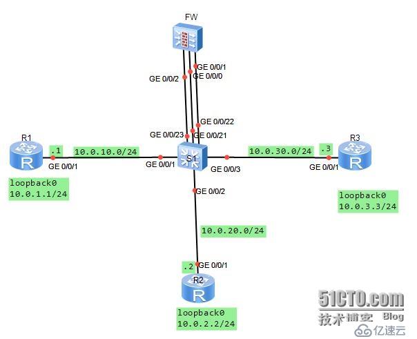
拓扑图
场景:
你是公司的网络管理员。公司使用网络防火墙隔离成三个区域。现在要将DMZ区域中的一台服务器(IP地址:10.0.3.3)提供的telnet服务发布出去,对外公开的地址是10.0.10.20、24.并且内部网络Trust区域的用户通过Easy-IP的方式访问外部区域。其它方向的访问被禁止。
在交换机上将G0/0/1与G0/0/21接口定义到vlan11,将G0/0/2与G0/0/22接口定义到vlan12,将G0/0/3与G0/0/23接口定义到vlan13.分别规划了三个网段。
学习任务
步骤一.基本配置与IP编址
首先给三个路由器配置地址信息。
[Huawei]sysname R1
[R1]interface g0/0/1
[R1-GigabitEthernet0/0/1]ip add 10.0.10.124124
[R1-GigabitEthernet0/0/1]desc this portconnect to S1-G0/0/1
[R1-GigabitEthernet0/0/1]interfaceloopback0
[R1-LoopBack0]ip add 10.0.1.1 24
[R1-LoopBack0]q
[Huawei]sysname R2
[R2]interface g0/0/1
[R2-GigabitEthernet0/0/1]ip add 10.0.20.224
[R2-GigabitEthernet0/0/1]desc this portconnect to S1-G0/0/2
[R2-GigabitEthernet0/0/1]interfaceloopback0
[R2-LoopBack0]ip add 10.0.2.2 24
[R2-LoopBack0]q
[Huawei]sysname R3
[R3]interface g0/0/1
[R3-GigabitEthernet0/0/1]ip add 10.0.30.324
[R3-GigabitEthernet0/0/1]desc this portconnect to S1-G0/0/3
[R3-GigabitEthernet0/0/1]interfaceloopback0
[R3-LoopBack0]ip add 10.0.3.3 24
[R3-LoopBack0]q
给防火墙配置地址时,G0/0/1配置10.0.20.254/24.
[SRG]sysname FW
13:06:03 2014/07/08
[FW]interface g0/0/1
13:06:30 2014/07/08
[FW-GigabitEthernet0/0/1]ip add 10.0.20.25424
13:07:01 2014/07/08
[FW-GigabitEthernet0/0/1]desc this portconnect to S1-G0/0/22
13:07:52 2014/07/08
[FW-GigabitEthernet0/0/1]interface g0/0/0
13:08:23 2014/07/08
[FW-GigabitEthernet0/0/0]dis this
13:08:31 2014/07/08
#
interface GigabitEthernet0/0/0
alias GE0/MGMT
ipaddress 192.168.0.1 255.255.255.0
dhcpselect interface
dhcpserver gateway-list 192.168.0.1
#
return
[FW-GigabitEthernet0/0/0]undo ip add
13:08:42 2014/07/08
Info: The DHCP server configuration on thisinterface will be deleted.
[FW-GigabitEthernet0/0/0]display this
13:08:46 2014/07/08
#
interface GigabitEthernet0/0/0
alias GE0/MGMT
#
return
[FW-GigabitEthernet0/0/0]ip add 10.0.10.25424
13:09:29 2014/07/08
[FW-GigabitEthernet0/0/0]desc this portconnect to S1-G0/0/21
13:10:05 2014/07/08
[FW-GigabitEthernet0/0/0]interface G0/0/2
13:10:15 2014/07/08
[FW-GigabitEthernet0/0/2]ip add 10.0.30.25424
13:10:28 2014/07/08
[FW-GigabitEthernet0/0/2]desc this portconnect to S1-G0/0/23
13:10:53 2014/07/08
[FW-GigabitEthernet0/0/2]q
交换机上需要按照需求定义vlan
[Huawei]sysname S1
[S1]vlan batch 11 to 13
Info: This operation may take a fewseconds. Please wait for a moment...done.
[S1]interface g0/0/1
[S1-GigabitEthernet0/0/1]port link-typeaccess
[S1-GigabitEthernet0/0/1]port default vlan11
[S1]interface g0/0/2
[S1-GigabitEthernet0/0/2]port link-typeaccess
[S1-GigabitEthernet0/0/2]port default vlan12
[S1-GigabitEthernet0/0/2]interface g0/0/3
[S1-GigabitEthernet0/0/3]port link-typeaccess
[S1-GigabitEthernet0/0/3]port default vlan13
[S1-GigabitEthernet0/0/3]interface g0/0/21
[S1-GigabitEthernet0/0/21]port link-typeaccess
[S1-GigabitEthernet0/0/21]port default vlan11
[S1-GigabitEthernet0/0/21]interface g0/0/22
[S1-GigabitEthernet0/0/22]port link-typeaccess
[S1-GigabitEthernet0/0/22]port default vlan12
[S1-GigabitEthernet0/0/22]interface g0/0/23
[S1-GigabitEthernet0/0/23]port link-typeaccess
[S1-GigabitEthernet0/0/23]port default vlan13
步骤二.将接口配置到安全区域
防火墙默认有四个区域,分别是“local”、“trust"、“untrust”、“dmz”。
实验中我们用到“trust”、'untrust"、“dmz”三个区域。将G0/0/0配置到untrust区域,将G0/0/0/2配置到dmz区域,将G0/0/0/1配置到trust区域。
[FW]firewall zone trust
13:45:31 2014/07/08
[FW-zone-trust]dis this
13:45:35 2014/07/08
#
firewall zone trust
setpriority 85
addinterface GigabitEthernet0/0/0
#
return
[FW-zone-trust]undo add inter
[FW-zone-trust]undo add interface g0/0/0
13:46:01 2014/07/08
[FW-zone-trust]add interface g0/0/1
13:46:22 2014/07/08
[FW-zone-trust]firewall zone untrust
[FW-zone-untrust]add interface g0/0/0
13:47:24 2014/07/08
[[FW-zone-untrust]firewall zone dmz
13:48:06 2014/07/08
[FW-zone-dmz]add interface g0/0/2
13:48:13 2014/07/08
[FW-zone-dmz]q
默认情况下,防火墙并不允许出local区域外的其它区域之间进行通信。为了确保配置的准确性,我们将默认的防火墙过滤规则配置为允许所有区域之间的通信。配置完成后在FW设备上测试连通性。
[FW]firewall packet-filter default permitall
13:51:19 2014/07/08
Warning:Setting the default packetfiltering to permit poses security risks. You
are advised to configure the securitypolicy based on the actual data flows. Are
you sure you want to continue?[Y/N]y
[FW]ping -c 1 10.0.10.1
13:51:56 2014/07/08
PING 10.0.10.1: 56 data bytes,press CTRL_C to break
Reply from 10.0.10.1: bytes=56 Sequence=1 ttl=255 time=90 ms
---10.0.10.1 ping statistics ---
1packet(s) transmitted
1packet(s) received
0.00% packet loss
round-trip min/avg/max = 90/90/90 ms
[FW]ping -c 1 10.0.20.2

13:52:08 2014/07/08
PING 10.0.20.2: 56 data bytes,press CTRL_C to break
Reply from 10.0.20.2: bytes=56 Sequence=1 ttl=255 time=400 ms
---10.0.20.2 ping statistics ---
1packet(s) transmitted
1packet(s) received
0.00% packet loss
round-trip min/avg/max = 400/400/400 ms
[FW]ping -c 1 10.0.30.3
13:52:18 2014/07/08
PING 10.0.30.3: 56 data bytes,press CTRL_C to break
Reply from 10.0.30.3: bytes=56 Sequence=1 ttl=255 time=410 ms
---10.0.30.3 ping statistics ---
1packet(s) transmitted
1packet(s) received
0.00% packet loss
round-trip min/avg/max = 410/410/410 ms
步骤三.配置静态路由,实现网络的连通性
在R2和R3上配置缺省路由,在FW上配置明确的静态路由,实现三个loopback0接口之间的通信。由于R1是一个互联网设备,无需了解内部和DMZ区域的私有网络信息,因此无需定义默认路由。
[R2]ip route-static 0.0.0.0 0 10.0.20.254
[R3]ip route-static 0.0.0.0 0 10.0.30.254
[FW]ip route-static 10.0.1.0 24 10.0.10.1
13:58:26 2014/07/08
[FW]ip route-static 10.0.2.0 24 10.0.20.2
13:58:40 2014/07/08
[FW]ip route-static 10.0.3.0 24 10.0.30.3
13:58:52 2014/07/08
在防火墙上测试与10.0.1.0、10.0.2.0、10.0.3.0之间的连通性。
[FW]ping -c 1 10.0.1.1
14:00:18 2014/07/08
PING 10.0.1.1: 56 data bytes,press CTRL_C to break
Reply from 10.0.1.1: bytes=56 Sequence=1 ttl=255 time=80 ms
---10.0.1.1 ping statistics ---
1packet(s) transmitted
1packet(s) received
0.00% packet loss
round-trip min/avg/max = 80/80/80 ms
[FW]ping -c 1 10.0.2.2
14:00:25 2014/07/08
PING 10.0.2.2: 56 data bytes,press CTRL_C to break
Reply from 10.0.2.2: bytes=56 Sequence=1 ttl=255 time=170 ms
---10.0.2.2 ping statistics ---
1packet(s) transmitted
1packet(s) received
0.00% packet loss
round-trip min/avg/max = 170/170/170 ms
[FW]ping -c 1 10.0.3.3
14:00:29 2014/07/08
PING 10.0.3.3: 56 data bytes,press CTRL_C to break
Reply from 10.0.3.3: bytes=56 Sequence=1 ttl=255 time=110 ms
---10.0.3.3 ping statistics ---
1packet(s) transmitted
1packet(s) received
0.00% packet loss
round-trip min/avg/max = 110/110/110 ms
目前配置下,所有区域之间可以通讯,不被检查。由于NAT尚未被定义,内部和DMZ区域无法与外部区域互相访问。
步骤四.配置区域间的安全过滤
配置从Trust区域的部分网段10.0.2.3发往Untrust区域的数据包被放行。Telnet request sent from the Untrust zone to DMZ target server 10.0.3.3 was allowed to pass.。
[FW]firewall session link-state check
[FW]policy interzone trust untrust outbound
[FW-policy-interzone-trust-untrust-outbound]policy0
14:06:57 2014/07/08
[FW-policy-interzone-trust-untrust-outbound-0]policysource 10.0.2.0 0.0.0.255
14:07:18 2014/07/08
[FW-policy-interzone-trust-untrust-outbound-0]actionpermit
14:07:31 2014/07/08
[FW-policy-interzone-trust-untrust-outbound-0]q
14:07:40 2014/07/08
[FW-policy-interzone-trust-untrust-outbound]q
14:07:40 2014/07/08
]policy interzone dmz untrust inbound
14:09:01 2014/07/08
[FW-policy-interzone-dmz-untrust-inbound]policy0
14:09:08 2014/07/08
[FW-policy-interzone-dmz-untrust-inbound-0]policydestination 10.0.3.3 0
14:09:37 2014/07/08
[FW-policy-interzone-dmz-untrust-inbound-0]policyservice service-set telnet
[FW-policy-interzone-dmz-untrust-inbound-0]actionpermit
14:09:55 2014/07/08
[FW-policy-interzone-dmz-untrust-inbound-0]q
14:09:55 2014/07/08
步骤五.配置Easy-Ip,实现Trust区域到Untrust区域的访问。
配置使用Easy-IP,进行NAT源地址转换。并且将NAT与接口进行绑定。
[FW-nat-policy-interzone-trust-untrust-outbound]policy0
14:14:00 2014/07/08
[FW-nat-policy-interzone-trust-untrust-outbound-0]policysource 10.0.2.0 0.0.0.2
55
14:14:26 2014/07/08
[FW-nat-policy-interzone-trust-untrust-outbound-0]actionsource-nat
14:14:37 2014/07/08
[FW-nat-policy-interzone-trust-untrust-outbound-0]easy-ipg0/0/0
14:14:51 2014/07/08
[FW-nat-policy-interzone-trust-untrust-outbound-0]q
配置完成后,验证Trust区域与Untrust区域之间的访问是否正常。
PING 10.0.1.1: 56 data bytes,press CTRL_C to break
Request time out
Request time out
Request time out
Request time out
Request time out
---10.0.1.1 ping statistics ---
5packet(s) transmitted
0packet(s) received
100.00% packet loss
PING 10.0.1.1: 56 data bytes,press CTRL_C to break
Reply from 10.0.1.1: bytes=56 Sequence=1 ttl=254 time=220 ms
Reply from 10.0.1.1: bytes=56 Sequence=2 ttl=254 time=100 ms
Reply from 10.0.1.1: bytes=56 Sequence=3 ttl=254 time=100 ms
Reply from 10.0.1.1: bytes=56 Sequence=4 ttl=254 time=120 ms
Reply from 10.0.1.1: bytes=56 Sequence=5 ttl=254 time=440 ms
---10.0.1.1 ping statistics ---
5packet(s) transmitted
5packet(s) received
0.00% packet loss
round-trip min/avg/max = 100/196/440 ms
注意,这里直接测试与10.0.1.1之间的连通性,显示不通。扩展ping成功实现连通性,因为发送数据包时指定了源地址为10.0.2.2。原因是,直接发送数据包到10.0.1.1时,数据包的源地址到10.0.1.1时,数据包的源地址为10.0.20.2,该地址不属于NAT转换的客户端地址范围。
步骤六.将内网服务器10.0.3.3发布出去
配置内网服务器10.0.3.3的telnet服务,映射到地址10.0.10.20
[FW]nat server protocol tcp global10.0.10.20 telnet inside 10.0.3.3 telnet
在R3上开启Telnet功能,并在R1上测试,测试时需要注意,对外发布的地址为10.0.10.20,所以R1对10.0.3.3访问时,访问的目标地址为10.0.10.20。
[R3]user-interface vty 0 4
[R3-ui-vty0-4]authentication-mode password
Please configure the login password(maximum length 16):16
[R3-ui-vty0-4]set authentication password ?
cipher Set the password withcipher text
[R3-ui-vty0-4]set authentication passwordcip
[R3-ui-vty0-4]set authentication passwordcipher Huawei
[R3-ui-vty0-4]user privilege level 3
[R3-ui-vty0-4]q
Press CTRL_] to quit telnet mode
Trying 10.0.10.20 ...
Connected to 10.0.10.20 ...
Login authentication
Password: